Pulse transformers
Technical description
UTK pulse transformers, normally used to drive semiconductors as thyristors and triacs, can transfer a square wave or a pulse with very short rise and fall times without appreciable distortion of the waveform. In such applications they provide both the firing pulse to the semiconductor’s gate, and the isolation between the low power control circuit and the power semiconductors, according to the international standards for the safety of the trans- formers.
UTK pulse transformers have the following characteristics.
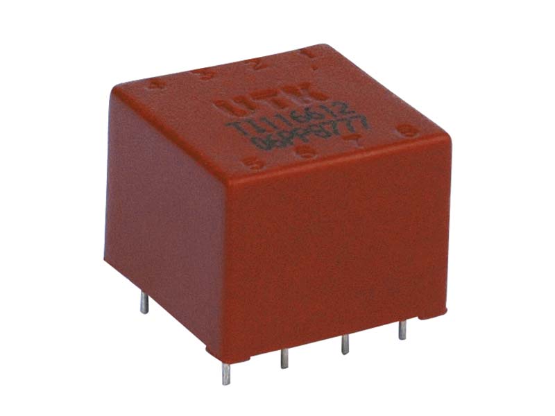
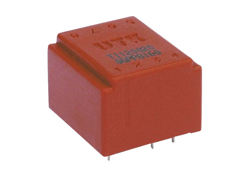
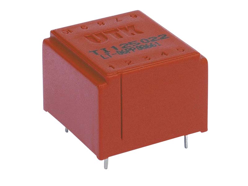
- Compact construction. They are vacuum-filled and encapsulated in plastic box made with self extinguis- hing material UL94-HB, suitable for the application on high density PCBs.
- Availability in a standard temperature range ( 0+80°) or an extended range
- Safe and reliable galvanic insulation
- Excellent magnetic coupling between the primary and secondary winding, which provides high fidelity in the transmission of the pulse having the shortest propaga- tion times, and a low magnetizing current.
- Transmission of high instantaneous power values
- High degree of immunity from noise and interference, thanks to the low coupling capacitance between primary and secondary.
- Low losses.
- Maximum working voltage up to 1KV. Dielectric strength tests are conducted according to the international standards EN61558 and EN60950.
A wide range of standard products is available for the driving of low to high power devices. In order to satisfy specific requirements UTK Component can develop spe- cial products according to the customers' needs.
UTK Component controls closely the production during the process and at the end of it, granting the quality and reliability of the product. The carried out tests include:
- Visual inspection
- Pinout and polarity check
- Value of the reference parameters ( n, Lp, Ld, Ck, Rp, Rs)
- Dielectric strength
Reference parameters
Winding ratio n
Turns ratio of the primary winding to the secondary.
Voltage time area ∫udt
Voltage time Integral on the secondary winding, or voltage time area. In case of application of unipolar pulse to the primary winding, ∫udt shows the maximum permitted value for the integral of secondary voltage, to avoid satu- ration of the magnetic core. Expressed in Vμs.
Rise time Ts
Time interval calculated on the rising slope of the secon- dary waveform, between 10% and 90% of the peak value, with resistive load equal to Rn and driving voltage 12V with duty cycle 50%. This parameter is mainly related to the quality of the magnetic coupling between the primary and the secondary winding and with the value of the leakage inductance Ld.
Peak current Ip
Maximum permitted secondary current
Load Resistance Rn
Nominal load resistance
Inductance Lp
Nominal value of inductance on primary winding. The maximum deviation from the nominal value ( tolerance) is +\-30%. Measured with LCR meter at the primary winding (Ambient temp 25°C, frequency 10KHz, drive UAC,rms=250mV).
Coupling capacitance Ck
Coupling capacitance between primary and secondary winding, depending on electric coupling of the coils. Low Ck values provide a high level of noise immunity to the firing circuit, preventing transmission of voltage spikes or high frequency noise coupling to the secondary and avoiding spurious triggering. Measured with LCR meter between the primary and secondary windings, with both windings shorted (frequency 10KHz, drive UAC,rms=250mV).
Winding resistance Rp,Rs
Resistance measured with LCR meter at the primary and secondary windings.