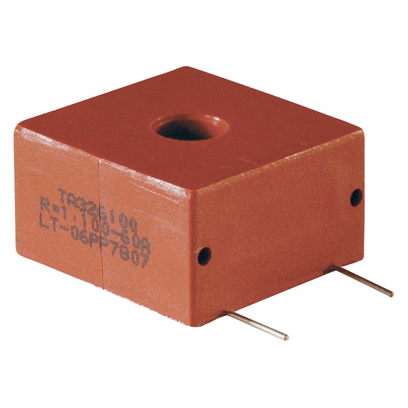
Current sense transformers
Technical description
UTK current sense transformers are normally used to detect switching currents in power semiconductors, for control, monitoring and protection purposes or to read the current in "current mode" control circuits. They are necessary in all applications where a galvanic insulation between the measured current and the measuring circuit is required. Unlike the current transformers used for measurement application, these devices don’t give very high accuracy. Their main application concerns in fact other factors, as for example cost and circuit simplicity, since they have to detect peak values or current trends rather than absolute values with the utmost precision.
In addition to the galvanic insulation between the power line and the control circuit, the current sensors give many advantages compared with resistive current sensing. The lower power dissipation of a current sense transformer allows a much higher signal level, improving the signal to noise environment of the control system. Unlike resistive shunts, where the resistance to inductance ratio is very poor, they also allow high working frequencies.
UTK Component current transformers have the following characteristics.
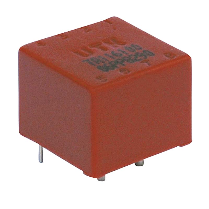
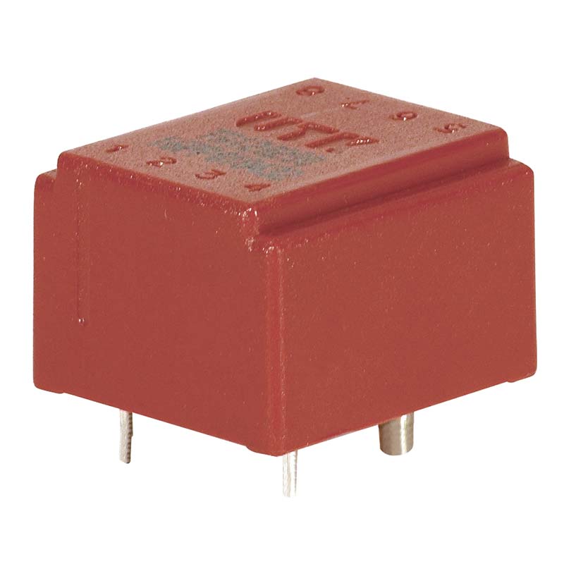
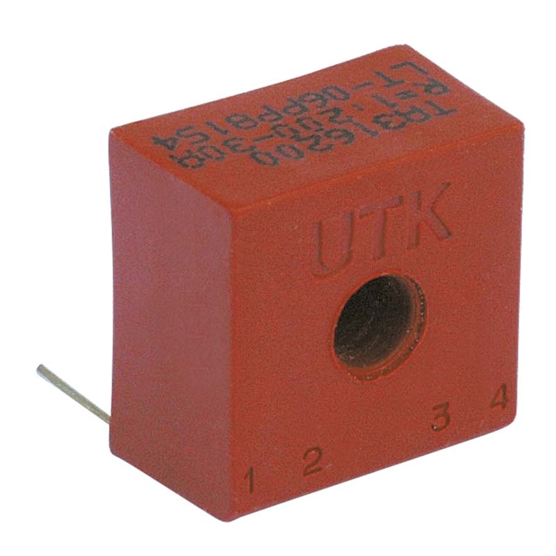
- Compact construction. They are vacuum-filled and encapsulated in plastic box made with self extinguishing material UL94-HB, suitable for the application on high density PCBs.
- Availability in a standard temperature range ( 0+80°) or an extended range
- High turns ratio, from 1:50 to 1:800
- Primary current from 20 to 100A
- High working frequency (from 40 KHz to 200KHz)
- Safe and reliable galvanic insulation
- Maximum working voltage up to 1KV. Dielectric strength tests are conducted according to the international standards EN61558 and EN60950.
- Low losses.
A wide range of standard products is available for the most common applications. In order to satisfy specific requirements UTK Component can develop special products according to the customers' needs.
UTK Component controls closely the production during the process and at the end of it, granting the quality and reliability of the product. The carried out tests include:
- Visual inspection
- Pinout and polarity check
- Value of the reference parameters
- Dielectric strength
Reference parameters
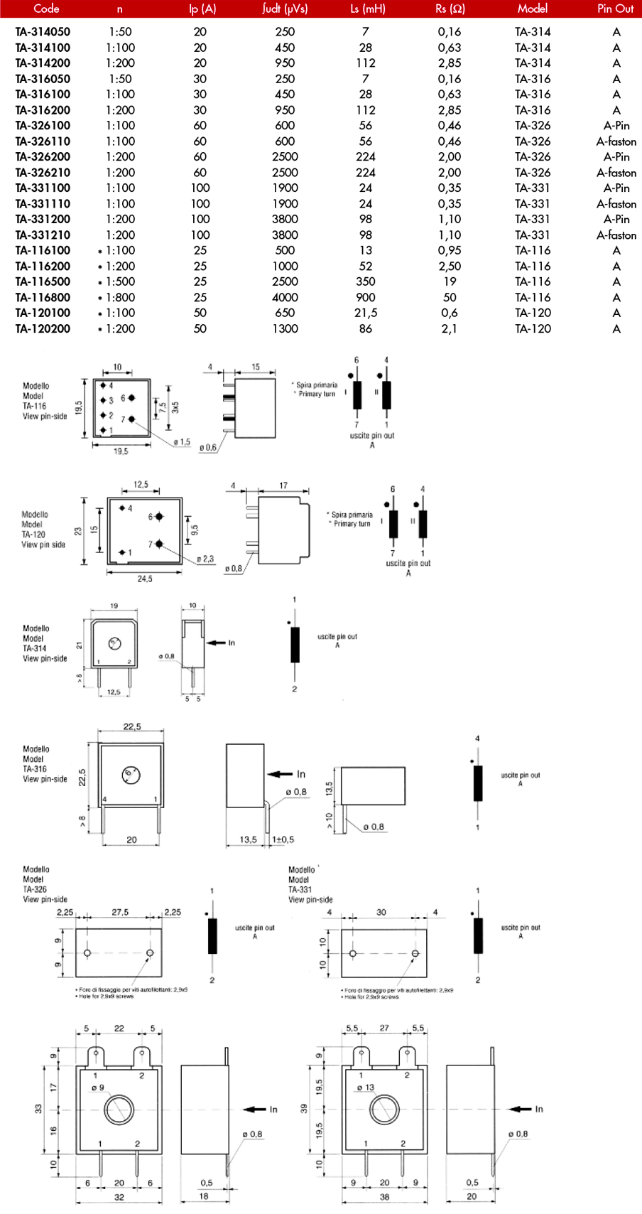
Winding ratio n
Turns ratio of the primary winding to the secondary. The primary winding is usually a single turn of high cross sectional area supplied by the user. A high winding ratio provides high secondary inductance, more accurate measures and lower insertion losses on the primary circuit.
Primary current Ip
Nominal value of the primary current, mainly related to the cross sectional area of the windings.
Voltage time area ∫udt
Voltage time Integral on the secondary winding, or voltage time area. In case of measure of unipolar pulses, ∫udt shows the maximum permitted value for the integral of secondary voltage, to avoid saturation of the magnetic core. Expressed in Vμs. Measuring circuits should provi- de adequate mechanisms for core demagnetization, also with very closely spaced pulses.
Secondary Inductance Ls
Nominal value of inductance on secondary winding. The maximum deviation from the nominal value (tolerance) is +\-25%. Measured with LCR meter at the primary winding (Ambient temp 25°C, frequency 10KHz, drive UAC,rms=250mV). The higher the inductance value, the lower the magnetizing current and more accurate the measure. Usually a magnetizing current equal to 10% of the primary current at the end of on time, gives a high quality measure in most applications.
Winding resistance Rs
Resistance measured with LCR meter at the secondary winding.
